CAD that knows how your part will be made

Draw a part, wire in the material and the machine that makes it, and CadFlow gives you the G-code or the DXF. It runs in your browser.

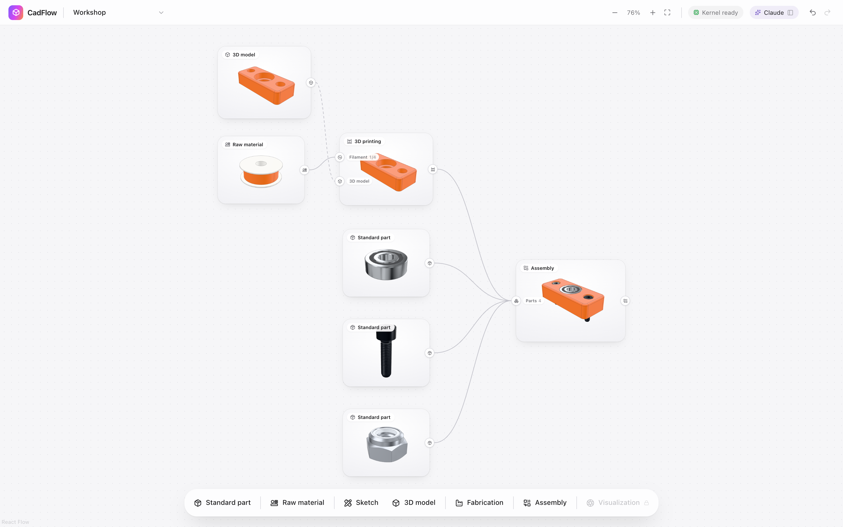
The CadFlow canvas: a 3D model and a spool of PLA wired into a 3D printer, and the printed part, a bearing, a screw and a nut wired into an assembly.

Design a part and slice it for your printer in one place

CadFlow checks every printed part the way a slicer sees it, then slices it with OrcaSlicer. You see each layer before the printer does.

Print time
22 min
PLA
10.9 g

The bearing block from CadFlow's example project, sliced with OrcaSlicer 2.4.2 for a Bambu Lab X1 Carbon, cut open at layer 40.
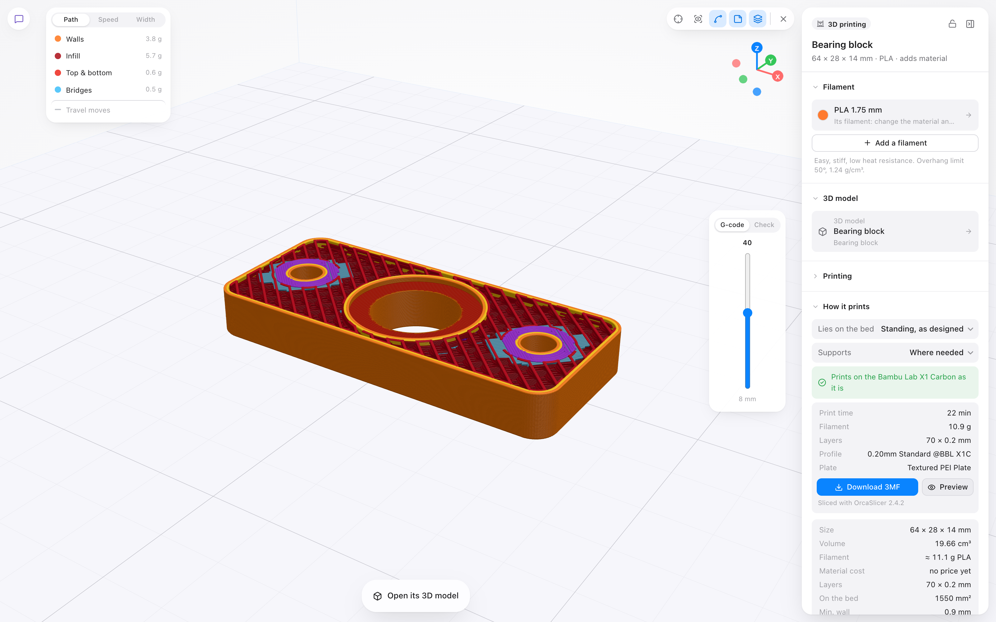
A printed part in CadFlow's print preview: OrcaSlicer's toolpaths, walls in orange and infill in red, cut open at layer 40, with the print time and filament beside it.

From raw material to finished part

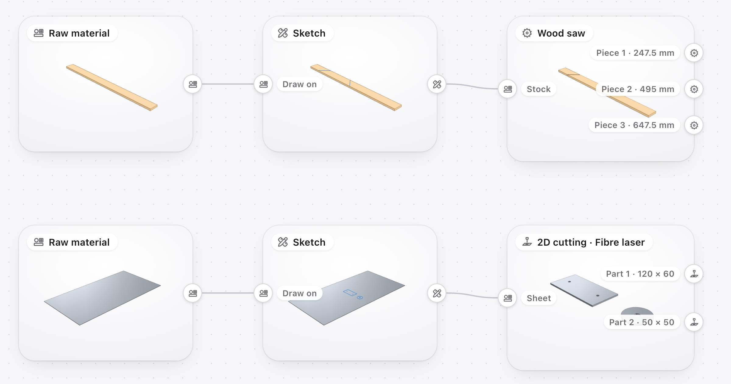
Wire a plank into a saw and it cuts along the lines you drew. Wire a steel sheet into a laser cutter and it cuts out the parts you drew on it.

Two rows of CadFlow blocks: a pine plank, a sketch with two mitre lines and a wood saw cutting it into three pieces; a steel sheet, a sketch with two parts and a fibre laser cutting them out.

Everything on one canvas

Every block on the canvas is live 3D, and wires carry what one block makes into the next. A 3D printer takes filament and a 3D model. A wood saw takes a plank, and it refuses a steel bar with a sentence saying why.

The CadFlow canvas: a 3D model and a spool of PLA wired into a 3D printer, and the printed part, a bearing, a screw and a nut wired into an assembly.

Mark it out, then cut where you marked

Draw on the stock the way you would pencil a line on a plank. The saw cuts along the lines you pick, and a laser cutter cuts out the shapes you pick, each one a part of its own with its own DXF.

Two rows of CadFlow blocks: a pine plank, a sketch with two mitre lines and a wood saw cutting it into three pieces; a steel sheet, a sketch with two parts and a fibre laser cutting them out.

Printed parts are checked before they're printed

CadFlow slices every printed part as it lies on the bed and finds pieces that would float and overhangs that need supports. OrcaSlicer then makes the G-code, and you can scroll through it layer by layer.

A printed part in CadFlow's print preview: OrcaSlicer's toolpaths, walls in orange and infill in red, cut open at layer 40, with the print time and filament beside it.

Bolt it together with real parts

Standard hardware comes from a library of ISO parts, from M2 screws to M20 bolts. Click a surface on one part and then where it goes on another, and the part moves there.

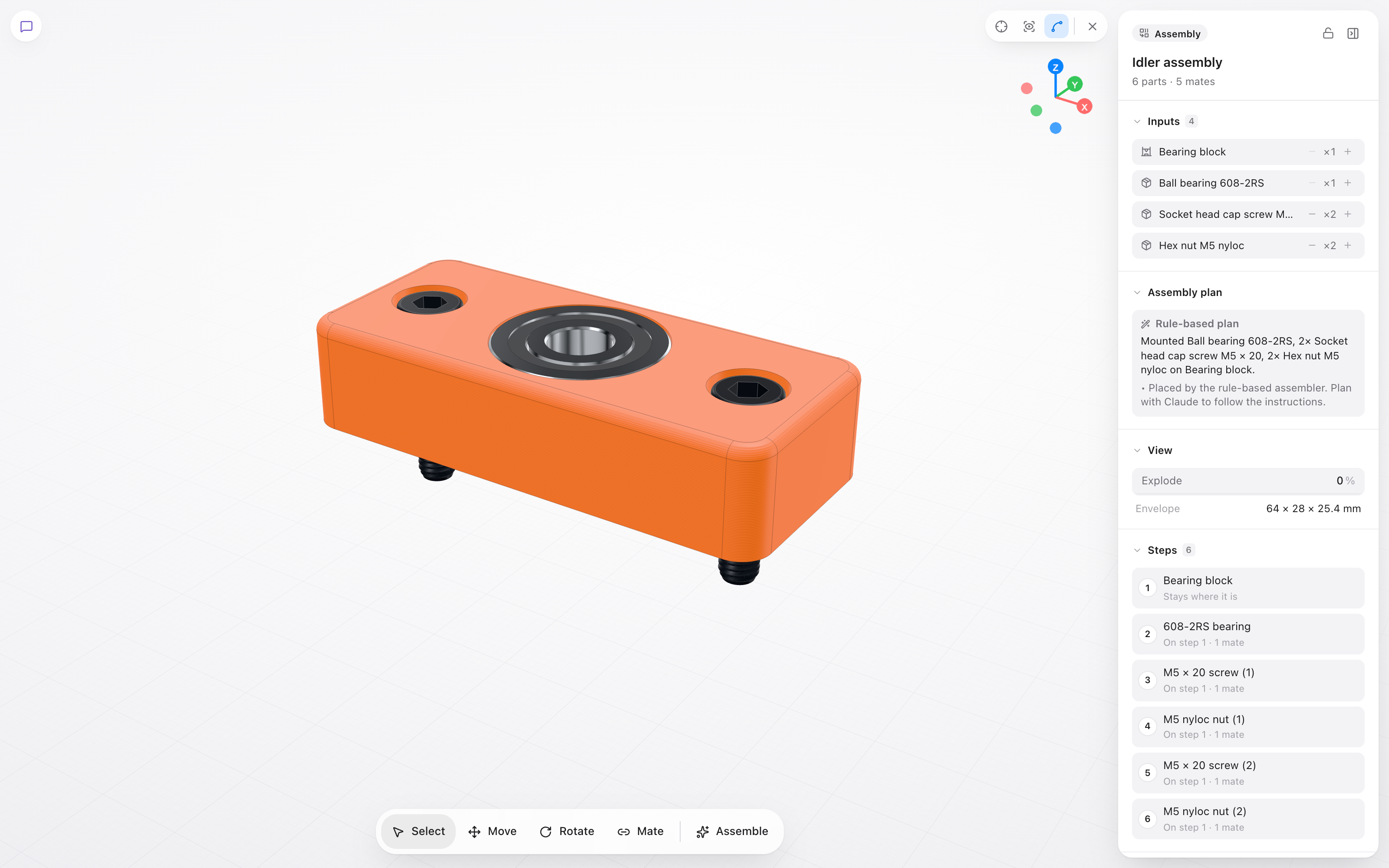
An assembly in CadFlow: a printed bearing block with a 608 bearing pressed into its seat and two M5 screws, with the steps that put each part in place.

From the blog

All posts

CadFlow isn't public yet

Leave your email and we'll write to you when you can try it.